Impedance-controlled PCBs

Why and when should impedance be controlled?

Impedance control for PCBs is important when high frequencies appear on the board. These frequencies might reflext, bounce back and overlap with each other. This can lead to misleading signals. In general you can talk about high frequency from frequencies of 1GHz up. If you have frequencies above you should look into the benefits of impendace controlled printed circuits. The biggest problem about a lack of impendance control is that the occurring errors are sporadic and can often not be repeated or simulated. You never know which bit gets through and which does not. Therefore it is important to assure signal integrity.
Which materials are suitable for impedance controlled PCBs?
For frequencies below 1GHz it is common to stick to standard FR4 materials. However, when frenquencies exceed the 1GHz signals may get lost. The important characteristig in material data sheets is the "loss factor" (tan delta), which only remains low for high freqnecies when dedicated HF-materials are used. We recommend materials from Rogers or Megtron6 from Panasonic. Boths are on stock and can also be calculated and ordered in our online calculation.
Are free impedance calculation tools sufficient?
Impedance control begins with a relatively easy planning of the required stack-up and the calculation of electro-magnetic effects surrounding the traces. Several free tools are available to estimate a first direction of the design. These tools are only suitable to check for a general feasibility, like if the requirements are evn close to being produced of completely out of range. For the exact impedance claculation we use and recommend the software of Polar Instruments (www.polarinstruments.com).
In this software not only the electro-magnetic effects are calculated, but by using the so-called "field solver", the influence and interdependency of the emitted fileds are put into consideration. This calculation is extremely compley, patented and the most accurate calculation available.

(source: http://www.polarinstruments.com/)

(source: http://www.polarinstruments.com/)
What is the difference between impedance control and impedance measurement?
Impendance control is the first step and generally possible without any measurement. All you need to do is select spcific materials, define the stack-up, trace width and trace distances. After produciton you may measure the real trace distances, board-stack-up etc. and apply these values to your pre-calculation. Using software from polar instruments you will get avery good indication on what the real impedance on your PCB will look like. This is a way to "control" the impedancewith simple tools.
However, this is still not a real and complete impedance measurement. We recommend to you to clarify with your supplier what "impendance control" really means. Are really impendaces measured or is it simply a thorough planning and cross-calculation of the actual phyisical appearanee?
How are impedances measured on PCBs?
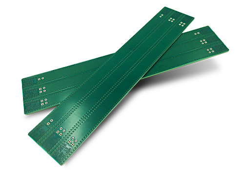
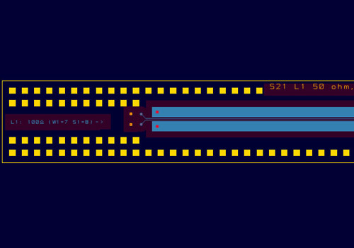
In order to really measure impedances on printed circuit boards so called "test coupons" are produced together with the PCB. These test coupons do look like real PCBs and depending on the number of impedances have a size between 150x10mm² and 150x60mm². These test coupons contain specially designed traces in accordance to the required impedances. Each production panel will then get at least one such test coupon on it. This incurs cost on the CAM design of such coupons as well as the used space on the actual production panel. Therefore, the etch rates and copper distribution reflect the exact same circumstances like the impedance controlled PCB and can be taken for measurement and direct comparison.
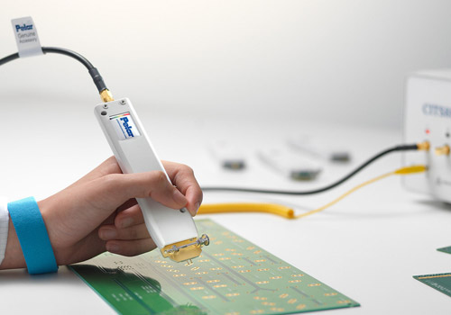
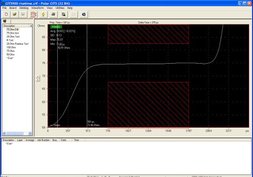
The reason such test coupon is needed lies in the special test-pads which are required for the Polar impedance measurement device. This machine can measure and document all impedances. The impedance controlled PCB itself is again not measured directly.

(source: http://www.polarinstruments.com/)

(source: http://www.polarinstruments.com/)
Which solutions does LeitOn offer?
You can already order the sole impedance calculation, prior to starting your layout. You only submit the target values of your suggested stack-up, trace structures, and target impendances. In case you do not know the stack-up yet, we might suggest one if you only tell us the layer quantity. We can then calculate the required stack-up and traces. With this information you can finalize your design. At a later point you can then come back to us and continue placing your order. You then select that LeitOn has already done the impedance calculation and that you only want to select the impedance measurement for PCB production.

(source: http://www.polarinstruments.com/)
In case you have used your own tool for impedance calculation and you are sure these calculations are correct, you can directly order the PCB with impedance measurement. However, we still need to make the impedance calculation because without it, Polar software has no information about what to measure.
All manufacturers differ in the materials and the production processes. Even with a fixed stack-up you will receive different impedance characteristics from different suppliers. This is why we explcitly recommend to let the PCB manufacturer do the impendance calculation. We also recommend to do it again, if you swith to another supplier. If you trust in your own calculation and experience, and you allow bigger tolerances, so that you do not want the additional impendace measurement, our experience tells us that this "might actually be enough". However, LeitOn can then take no responsibility or guarantee.
Another good reason to better order the impedance measurement is that standard-PCBs are combined with other layouts on th production panel. This leads to slightly different lamination thicknesses from the calculated values. Standard PCBs might also be produced on higher TG materials so that the calculated dielectric constant differs.
Conclusion: Only if you order impendace measurement with your printed circuits we can actuall guarantee that the impendances on your PCB are within the target range.
Which tolerances are commen for impendance controlled PCBs?
A typical tolerance is +/-10% for impendances. This tolerance applies to the online calculation and is an industrial standard.
however, in some cases tighter tolerances might be achieved, e.g. 100 Ohm +/-5 Ohm. This often requires a pre-production run folloowed by adjusting some values prior to the actual batch production. In such cases, please enquire.


