
Rogers PCB | HF | Printed circuit board | PCB | RO4003 | RO4350 | RO4360
Rogers PCB (HF printed circuit boards & PCBs) - RO4003, RO4350, RO4360 & Co.
High Frequency - the Highest Art! High arts require perfect conditions and equipment of the highest quality.
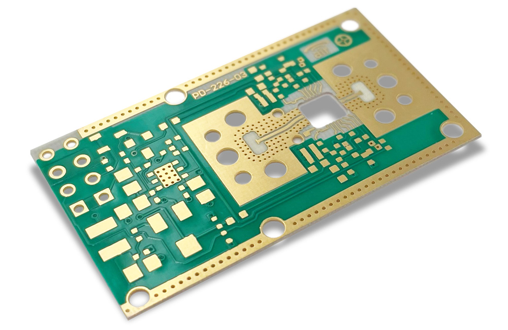
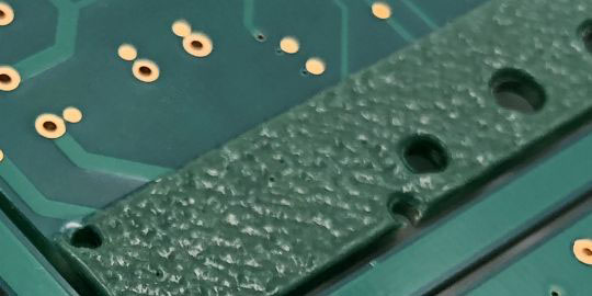
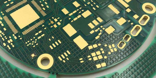
When it comes to high-frequency technology, nothing can bypass Rogers printed circuit boards. Rogers base material offers excellent signal integrity and low losses for 'fast circuits' starting from 1GHz. Additionally, Rogers boasts excellent thermal stability, is robust, and heat-resistant.
LeitOn provides all thicknesses of the Rogers 4003C, 4350B, and 4360G2 series in stock and even in the online calculation. In addition to pure Rogers multilayers, hybrid multilayers made of FR4 prepregs and Rogers cores complement the range of high-frequency solutions with a cost-effective and readily available technology. Our technical advisors are always available to assist you with any questions.


Options |
|---|
| Characteristic | Values/specifications |
| Material types | 4003C, 4350B, 4360G2 |
| Material manufacturers | Rogers |
| Material thicknesses | 0,1 mm to 1,52 mm |
| Maximum PCB size | 445 x 293 mm², over-sized PCBs on enquiry |
| Copper thicknesses | 18µm / 35µm |
| Layer count | 1 to 12 layers |
| Surface finishes | HAL-lead free, HAL, ENIG, ENEPIG, immersion tin, immersion silver, OSP, hard gold, others on enquiry |
| Mechanical machining | Routing, v-cut (scoring), jump v-cut, bevelling, depth milling, counter-sink holes |
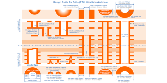
| Drill options | Micro-vias, blind-vias, laser-vias, stacked-vias, pressfit |
| Metallizations | Plated edges (restricted), plated half-open, plated slots, plated depth milling |
| Solder mask | Lacquer, high-reflection lacquer, coverlay Coverlay colors: yellow, white, black Lacquer colors: green, black, red, blue, yellow, white, custom colors and matt lacquers |
| Special prints | Peelable mask, carbon print, UV-reflection coating, silk screen print |
| Special technologies | Rogers-FR4 hybrid multilayer, 3mil structures, coil structures, special stack-ups, impedance measurements, plugging, filling (restricted) & tenting, copper-via-filling |
| Quality Management & certifications | ISO 9001, ISO 14001, UL, IPC2/IPC3, IATF 16949, ISIR, VDA2, PPAP, cross sections, measurement reports, certificate of conformity, data sheets, ESD-packing etc. |
| Logistics | Frame-orders, consignment warehouse, call-orders, sea-air-split-orders |
Definition: Rogers PCB
Rogers PCBs (Printed Circuit Boards) are RF circuit boards that are manufactured from special high-frequency substrate materials, which possess outstanding technical characteristics and ensure better controllable impedances (alternating current resistance) in electronics starting from 1GHz. Additionally, they exhibit high thermal stability and mechanical strength. LeitOn primarily utilizes high-frequency substrate materials from the world leader Rogers, which is specifically focused on high-frequency applications.
Material & components of Rogers PCB
Rogers materials are composed of a combination of different components to achieve desired properties based on the frequency application range and usage. Here's a brief overview of the individual components of Rogers materials:
Glass Fabric: An essential component of many Rogers substrates is high-quality glass fiber fabric, also known from FR4. This glass fiber fabric provides strength and stability. In the Rogers 3000 series, glass fiber is omitted, and stability is achieved through fillers only.
Fillers: Ceramic fillers are used to improve dielectric properties and achieve a stable dielectric constant. They also contribute stabilizing properties. In the Rogers 5000 series, for instance, glass microfibers are used to maintain Dk uniformity (uniformity of the dielectric constant). Other fillers are used to optimize thermal conductivity or enhance flame retardation.
Resins: Different resins are used depending on the series. The resins in the 4000 series are cost-optimized thermosetting plastics. For higher-frequency requirements, more expensive PTFE (e.g., RO3000 series and Rogers 5000/6000 series) are typically used. Epoxy resins can be found in FR4-based materials from more affordable manufacturers like Panasonic (MEGTRON) or Isola (IS620, among others).
Rogers Corporation as a market leader in technical materials
The Rogers Corporation is a leading company in the development and manufacturing of high-performance materials for various industries. With over 180 years of experience, the company provides innovative solutions for demanding applications in the fields of electronics, high-frequency technology, renewable energy, transportation, and more.
With offices and production facilities around the world, the Rogers Corporation is dedicated to supporting engineers with top-notch service and support. The company is committed to continuous improvement and drives innovation to meet the changing demands of the industry.
This is what makes Rogers PCB stand out
All Rogers materials have well-controlled dielectric constants (Dk) that cover a wide range depending on the product group. In addition to above-average thermal conductivity (0.6 to 0.8 W/mK), they also possess high thermal robustness (lead-free solder compatibility) and a low Z-axis expansion for reliable quality of plated-through holes. Specifically, the RO4000 series offered in stock by LeitOn provides optimized costs and high-frequency/microwave performance, for example, through compatibility with FR4 manufacturing processes and even flame-retardant versions compliant with UL 94 V-0.
Application possibilities of Rogers PCB
Rogers circuit boards are used in a variety of applications, especially in areas where precise high-frequency signals are crucial. Examples of these include:
- Telecommunications
- High-frequency technology
- Radar technology
- Satellite systems
- Microwave applications
The different types of Rogers PCB
Rogers categorizes its materials primarily into series, each with distinct technical properties. The main series are RO3000, RO4000, as well as Rogers RT/duroid (or RO5000 and RO6000 series) and Rogers TMM laminates.
Rogers 4000 Series (Standard at LeitOn)
Rogers RO4000 hydrocarbon ceramic laminates and prepregs are industry leaders among RF base materials. These materials are used by customers for their low attenuation at microwave and millimeter-wave frequencies. The RO4000 series offers easier processing in PCB manufacturing compared to conventional PTFE materials and optimized characteristics. Its compatibility with FR4 manufacturing processes makes it significantly more cost-effective than corresponding PTFE materials.
RO4003C was developed with a dielectric constant (Dk) of 3.38. It is ideal for high-volume, performance-critical RF applications at comparatively low costs.
RO4350B is an alternative to RO4003C with a dielectric constant (Dk) of 3.48. RO4350B is UL 94 V-0 certified.
RO4360G2 has a relatively high Dk value of 6.15, which is otherwise only found in considerably more expensive RO5000/RO6000 series PTFE materials.
RO4450F is the standard prepreg type for Rogers multilayer boards, based on RO4000 series core materials. RO4450F is a CAF-resistant high-frequency thermosetting prepreg, compatible with FR4 lamination temperatures, enabling cost-effective production of high-frequency multilayer circuits.
Other Rogers Series
Rogers 3000 Series
Rogers RO3000 high-frequency base materials are ceramic-filled PTFE composites designed for use in commercial microwave and RF applications. This advanced laminate family offers exceptional electrical and mechanical stability. They have the lowest loss tangent (Df) among Rogers laminates. The RO3000 series is available in a wide Dk range from 3.0 to 10.2. Common types include RO3003, RO3006, and RO3010, where the last digits always indicate the value of the dielectric constant, for example: RO3003 = Dk 3.0 / RO3006 = Dk 6.0, and so on.
Rogers RT/duroid®
Rogers RT/duroid® high-frequency base material is a filled PTFE composite laminate (with optional glass or ceramic) designed for aerospace and defense applications. The Rogers RT/duroid® series surpasses most other Rogers series in terms of technical properties:
- Lowest electrical loss
- Lowest moisture absorption
- Highly stable dielectric constant (Dk) across a wide frequency range
- Minimal outgassing (important in aerospace applications)
The most common materials in the Rogers RT/duroid series (RO5000/RO6000) are RO5870, RO5880, and RO6002.
Rogers TMM Laminates
Rogers TMM laminates are thermosetting microwave laminates that can also be processed into 3D-formed parts. Consequently, Rogers TMM base materials are highly costly. The most frequently used types are TMM4 and TMM10, where the numbers indicate the approximate Dk value at a reference frequency of 10GHz (TMM4 = Dk value 4.5).
The production of our printed circuit boards

The manufacturing process of Rogers circuit boards involves several steps to ensure high-quality products with precise electrical characteristics.
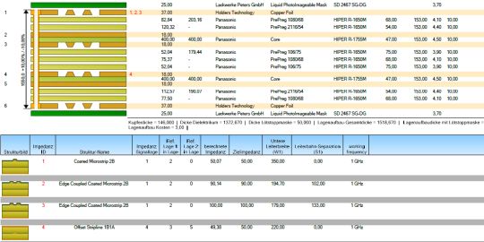
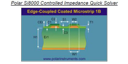
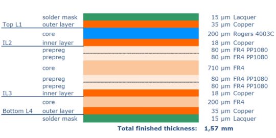
Material Selection: Selecting the right Rogers material based on application requirements is crucial. Depending on the required impedance and layer count, material type, thickness, and necessary prepregs are chosen. All is done according to calculated impedances and designs using Polar Instruments software.
- Substrate Preparation: The core material is prepared by cutting it to the desired size and thickness. The surface is chemically cleaned and prepared for further processing.
- Drilling & Plating Through Holes: Rogers cores are drilled and then plated through (for double-layer Rogers PCBs). For multilayer boards, this step is carried out after Step 6.
- Photolithography: Using photomasks, a pattern is applied to the copper layer, defining the traces and component positions on the board.
- Etching: Unwanted copper areas are removed through etching processes, preserving the defined traces and components.
- Multilayer Pressing: If more than two layers are required, the PCB's inner layers are pressed together with prepregs in a sandwich structure at high temperatures.
- Solder Mask & Screen Printing: A solder mask is applied to protect the solder pads, while silk screen printing is used for labeling and applying markings.
- Surface Finishing: The board undergoes surface finishing to provide corrosion resistance and improve solderability.
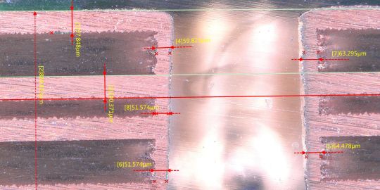
- Testing and Inspection: Each finished board is tested for electrical continuity, insulation resistance, and error-free operation, and visually inspected to ensure it meets quality standards.
The manufacturing process of Rogers circuit boards demands precision, expertise, and modern production facilities to create high-quality products with the desired electrical characteristics.
Buy affordable Rogers PCB printed circuit boards online at LeitOn
Calculate and purchase top-quality Rogers PCB circuit boards and panels at affordable prices from LeitOn! (Link to Rogers Calculator) Our user-friendly online platform allows you to calculate your Rogers circuit boards in various configurations and with diverse options. Feel free to contact us personally via email, inquiry form, or phone. Benefit from our experience and expertise in PCB manufacturing. Easy, fast, and reliable!
Rogers PCB stands for "Rogers Printed Circuit Board" (printed circuit boards using Rogers base material). Rogers PCBs are made from a specialized material called Rogers high-frequency substrate. This substrate is renowned for its excellent electrical properties in high-frequency applications. Rogers PCBs offer high stability, good heat dissipation, and low moisture absorption. They allow for precise manufacturing and are generally more expensive than conventional PCB materials due to their specific characteristics and production process.
The Rogers material for circuit boards offers various advantages, particularly in high-frequency applications:
- Precise Dielectric Constant (Dk): The dielectric constant varies depending on the specific Rogers material type. Some Rogers substrates have a low Dk of about 2 to 6, while others can have higher Dk values of 8 to 12 or even higher.
- Low Loss Tangent (Df): Rogers material has a low loss tangent, which means it absorbs only small amounts of energy and minimizes losses. This is particularly important for high-frequency applications where precise signal transmission and minimal signal distortion are required.
- High-Temperature Stability: Rogers substrates are known for their high thermal stability. They can be used at high temperatures without significant changes in their physical and electrical properties. This is important to ensure reliable performance under demanding operating conditions. In some cases, Rogers is used not just for its RF properties, but also due to its high temperature resistance.
- Low Moisture Absorption: Rogers substrates absorb minimal amounts of moisture compared to some other materials. This reduces the risk of moisture-related damage or performance changes, especially in high-humidity environments.
Rogers Corporation offers various types of materials designed for different applications and requirements. Here are some of the well-known product lines of Rogers materials:
- RO4000 Series: This series comprises high-frequency substrates with low dielectric constants (Dk) and low loss tangent (Df). The RO4000 series is characterized by improved performance at high frequencies, providing precise signal transmission with minimal losses. They are often used in high-frequency applications such as wireless communication systems, radar systems, and antennas.
- RO3000 Series: The RO3000 series also offers materials with low Dk and low Df. This series excels in performance at medium to high frequencies. RO3000 is frequently utilized for antennas.
- RO6000 Series: The RO6000 series includes high-performance laminate materials developed for demanding applications with extreme environmental conditions and high-performance requirements. In comparison to RO4000 and RO3000 materials, some of the RO6000 materials have higher dielectric constants (Dk). The RO6000 series also provides good heat dissipation and stability at high temperatures. They are used in aerospace, defense technology, and high-performance electronics.
Rogers PCB and FR4 PCB are two different types of circuit board materials widely used in the electronics industry. Here are the key differences between them:
- Material Composition: Rogers PCB is based on specialized composite materials developed by Rogers Corporation. These materials consist of a combination of glass fibers and thermoplastic resins with specific additives. On the other hand, FR4 PCB uses a standard glass fabric impregnated with an epoxy resin matrix.
- Dielectric Properties: Rogers PCB offers better performance in high-frequency applications. They have a specific, precise dielectric constant (Dk) depending on the type and generally a lower loss tangent (Df), leading to reduced signal losses and more accurate signal transmission. In comparison, FR4 PCB has a less precise Dk and a higher Df, which can result in somewhat higher losses in high-frequency signals.
- High-Frequency Performance: Due to their lower losses and improved signal integrity, Rogers PCBs are commonly used in high-frequency applications such as wireless communication systems, satellite communication, and radar systems. FR4 PCBs are suitable for lower frequency applications like standard electronics and general-purpose tasks.
- Cost: Rogers PCBs are generally more expensive than FR4 PCBs due to their specialized composition and improved high-frequency characteristics.
The choice between Rogers PCB and FR4 PCB depends on the specific requirements of the application. If precise signal transmission in high-frequency signals is needed, Rogers PCBs are the better choice. For lower frequency applications and general requirements, FR4 PCB might be a more cost-effective option.
Rogers PCBs are commonly used in the electronics industry, particularly in applications that require high frequencies, low losses, and precise signal transmission. The Rogers substrate is characterized by a low loss tangent, resulting in minimal signal distortion and improved performance. Rogers circuit boards are often utilized in applications such as high-frequency communication systems, wireless networks, satellite communication, radar systems, antennas, mobile base stations, aerospace, and medical technology.
The use of Rogers PCB materials is typically recommended when frequencies above 1 GHz are to be achieved. Rogers materials have been specifically developed for high-frequency applications and offer exceptional electrical properties such as low loss tangents (Df), which are crucial at such frequencies. These materials allow for minimal signal losses, thus ensuring more stable functionality.
The TG ("Glass Transition Temperature") of Rogers PCB materials varies depending on the specific material type. Rogers Corporation offers various materials, each with a different TG value. Typically, the TG values for Rogers PCB materials range from around 150°C to 280°C. This high TG temperature allows the circuit boards to be used in elevated temperature environments, as the material maintains its structural integrity even at high temperatures. It's important to check the TG value of the specific Rogers material being used for your application to ensure it can withstand the thermal requirements.
Rogers offers a wide range of different materials with varying dielectric constants (Dk).
Here are some examples, based on a reference frequency of 10 GHz:
- RO4232: Dk value of approximately 2.20
- RO5880: Dk value of approximately 2.20
- RO4730: Dk value of approximately 3.00
- RO3003C: Dk value of approximately 3.00
- RO4533: Dk value of approximately 3.30
- RO4003C: Dk value of approximately 3.38
- RO4780: Dk value of approximately 3.38
- RO4350B: Dk value of approximately 3.48
- RO6035: Dk value of approximately 3.50
- RO4450F: Dk value of approximately 3.52
- RO6002: Dk value of approximately 6.15
- RO3006: Dk value of approximately 6.15
- RO3010: Dk value of approximately 10.2
- RO3203: Dk value of approximately 10.2
- RO3206: Dk value of approximately 10.2
Rogers offers additional materials with other dielectric constants as well. If you have a specific requirement, we would be happy to assist you with material selection.
The Rogers material with the highest operating temperature is RO4835T, which can be used at a continuous operating temperature of up to 230°C. RO4835T is a high-performance material designed for applications in extreme temperatures, offering excellent thermal stability and reliability. Please note that the exact operating temperature of RO4835T can depend on other factors such as material thickness, construction, and environmental conditions. It's always advisable to refer to the specific technical datasheets of the material to determine precise operating temperatures and limitations.
Here are the key properties of Rogers PCB materials for high-frequency applications:
- Low electrical losses: Rogers materials typically exhibit low electrical losses, resulting in improved signal integrity and reduced attenuation in high-frequency signals.
- Wide frequency range: Rogers materials provide good performance across a wide frequency range, making them suitable for various high-frequency applications.
- Good thermal stability: Rogers materials have a high glass transition temperature (TG), meaning they maintain their structural integrity even at elevated temperatures, making them suitable for applications with high heat generation.
- Consistent dielectric constant: Rogers materials can offer a consistent dielectric constant over a specific frequency range, leading to precise signal transmission and consistent performance.
- Mechanical strength: Rogers materials are generally mechanically robust and offer good dimensional stability, resulting in reliable and durable circuit board manufacturing.
These properties make Rogers PCB materials a preferred choice for high-frequency applications, as they offer good performance, reliability, and thermal stability. The precise selection of the appropriate Rogers material depends on the specific requirements of the application and frequency range. We are happy to provide guidance and advice!

since 2021
- CO2 neutral through compensation
- Circuit boards – green on the outside, also on the inside

- Expertise through active exchange
- Expertise through training and further education
- ISO 9001:2015 Quality Management
- ISO 14001:2015 Environmental Management

- UL for rigid FR4 PCBs
- UL for flexible circuit boards
- UL for aluminum IMS boards


