
Flex PCB | flexible printed circuit board | FPC
Flex PCB - Flexible FPC printed circuit boards
Flexible boards with a lot of know-how
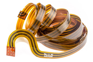
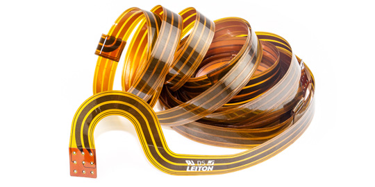
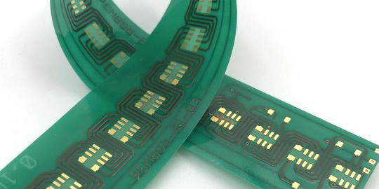
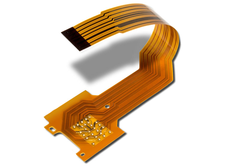
Printed circuits are not only carriers of electronic components, but also the connecting tracks between them. Flexible printed circuit boards thus enable the first step towards the 3D design of entire assemblies or can replace cables. They are also dynamically flexible and can therefore be used reliably in moveable devices. It is important to adapt the design to future mechanical loads on the FPC. Little things can make a big difference in bending loads. Here, we offer you the appropriate know-how in consulting and production.
For example, outlines should always be rounded and have no inner edges. Conductor tracks should also not run at 90° angles, or vias must be routed outside of bending areas. Reinforcements are highly recommended in areas with SMD components, but these should not border directly on any bending area. Openings in the coverlay can also result in unwanted cut edges and must be well planned. These are just examples, the list of considerations is long. We would be happy to advise you at an early stage on your FPC design.
FPC prototyping to series production
LeitOn helps you to turn the first FPC prototype into a design suitable for series or mass production. An online calculation is available 24/7 for samples and small series, in which flexible printed circuits can be calculated and ordered. A comprehensive information area in the special technologies presents additional options that can support the planned area of application even more specifically.


Options |
|---|
| Material properties | Adhesive-free, adhesive-based polyimide (PI), halogen-free, PET |
| Material manufacturers | ITEQ, ShengYi |
| Material thicknesses | 12.5µm to 65µm plus copper & coverlay |
| Maximum PCB size | 1- and 2-layer 234x374mm² to 230x580mm², oversizes on request |
| Copper thicknesses | 18µm / 28µm / 35µm / 70µm |
| Layer count | 1 to 6 layers |
| Surface finishes | ENIG, ENEPIG, chemical silver, OSP, hard gold |
| Mechanical machining | Laser cutting, punching |
| Drill options | micro vias |
| Metallizations | Edge metallization, stamp contours, half-opens, slotted holes, plated slots |
| Solder mask | Coverlay, flex varnish, mixture "flex varnish & coverlay" |
| Special prints | silkscreen |
| Special technologies | Stiffeners PI or FR4, 3M adhesive, endless flex, dimples, component carriers, 2mil structures, coils, special layer stack-ups, shielding-foil |
| Quality Management & Certifications | ISO 9001, ISO 14001, UL, IPC2/IPC3, IATF 16949, EMPB, VDA2, PPAP, cuts, measurements, declarations of conformity, data sheets, ESD packaging |
| Logistics | Framework orders, consignment stock, call-off stock, sea-air split orders |
Flexible PCB (FPC)
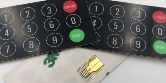
Flexible PCB are flexible printed circuit boards, where the PCB stands for "printed circuit board". The correct abbreviation for flexible printed circuit boards would be FPC for "flexible printed circuit", since the "B" for "board" would be a "plate" and therefore rigid. Colloquially, the term “flexible PCBs” is widely used. Like conventional, rigid printed circuit boards, flexible printed circuits can be used as carriers for the electrical connection of components. A far more common use, however, is to connect rigid circuit boards together, as a type of cable, or as a flexible extension for positioning e.g. sensors. Flexible PCBs are also used as keypad foils.
Advantages of flexible printed circuits
The advantages of flexible printed circuits (FPC) are manifold:
- flexible
- very thin
- Flame-retardant, class 94V0
- solderable
- inexpensive
- customizable
Furthermore, flexible printed circuit boards can be expanded with various special options for special applications, such as shielding foil, partial stiffening or “dimples” for better contacting, such as with ink cartridges on a printer.
Material & properties of Flex PCB
A typical material for flexible circuit boards is polyimide (not to be confused with polyamide). Polyimide itself has a higher temperature resistance than the standard FR4 material used for rigid PCBs. However, many flex PCBs also use epoxy, e.g. when a masking film is applied as a solder stop. There are also various flexible base materials, some of which contain layers of epoxy. For example, epoxy is used to apply the copper layer to the polyimide. As a result, the temperature resistance of the entire flexible printed circuit board is reduced again compared to pure polyimide (adhesive-less material).
Types of flexible printed circuit boards (FPC)
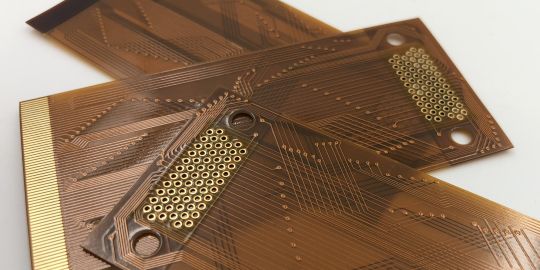
With flexible printed circuit boards, a basic distinction must be made between adhesive-free (or adhesive-less) and adhesive-based material. Adhesive-less FPCs do not contain epoxy in the base film (as the base material of FPC is also called because it is so thin). Here, the copper is rolled (annealed) directly onto the polyimide. Adhesive-free materials are therefore usually even thinner and are used when, for example, there are higher temperature requirements or epoxy must not be present in the application for other reasons.
Flexible printed circuit boards
With adhesive-based FPCs, the copper is bonded to the polyimide with a thin layer of epoxy. So you have thin, flexible mixed material structures. This is the cheaper and more common type of FPC base material and has no disadvantages compared to adhesive-free material for normal requirements.
Rigid-flex printed circuit boards
Another evolutionary stage of the flexible circuit FPC is the so-called rigid-flex PCB or rigid-flex circuit board. The abbreviation for this is “RFPCB”, which stands for “Rigid-Flexible Printed Circuit Board”. This is a combination of each one or even more rigid and flexible printed circuit boards in one circuit design. Since rigid-flexible printed circuit boards are a completely separate technology, we have compiled the information for you here.
The production of our printed circuit boards
The manufacturing process for flex circuit boards FPC is largely the same as for the manufacture of rigid circuit boards, with the biggest exception of handling. There are certain differences in the application of coverlay instead of wet solder mask. Here, a adhesive-based coverlay is used, in which the openings for the pads have been cut out beforehand. Due to FPCs sensitivity, some surface treatments are done with chemical processes, rather than mechanical ones. Another deviation is the separation, since flex circuit boards are usually either lasered or punched.
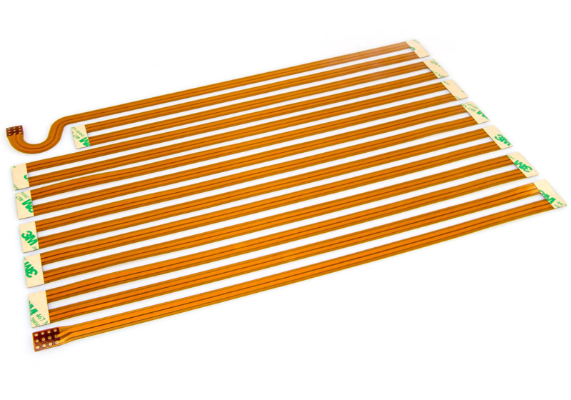
Common FPC Addons - Stiffeners & 3M
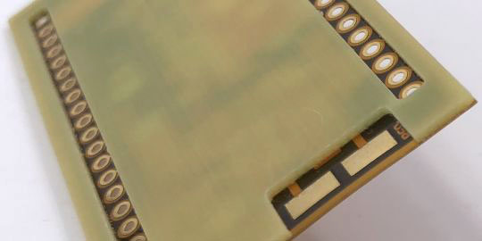
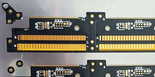
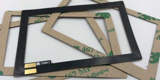
In order to use flexible printed circuit boards in their application in an even more targeted manner, the usual additions are stiffeners (reinforcements) and 3M adhesive foils. On the one hand, stiffeners are used to reinforce flex connector areas to a certain thickness (usually to a total thickness of 0.3mm), so that these connector ends can be plugged directly into sockets (usually ZIF/LIF). Such stiffeners are usually made of polyimide. Other reinforcements can also be made of FR4 and stabilize areas where components are placed, for example. Because components should never be located in bendable areas, as these could then break off quickly under load.
3M film is a double-sided adhesive film that allows the flexible circuit boards to be placed partially or over the entire surface like a sticker in an application. The 3M adhesive we use is suitable for reflow soldering. Both options are available in our online calculation.
Buy affordable flex printed circuit boards (FPC) online directly from manufacturer
LeitOn offers industrially manufactured, inexpensive flex boards in the online calculation or on request by mail. In our online calculation you can choose between different materials, for example between adhesive-free and adhesive-based polyimide. Different thicknesses of stiffeners for ZIF/LIF connectors can also be attached, or a partial 3M adhesive film for easy gluing of the flex PCB into their application later. Other special options for FPCs you can find on our special technology site.
FPC stands for "Flexible Printed Circuit" and is - as the name suggests - a flexible printed circuit board. Flexible printed circuit boards, like rigid printed circuit boards (PCB), serve to support the connection of electronic components. FPCs are also often used as cables and are very bendable or even dynamically resilient (many millions of bends). Copper is used as the conductive material in most cases, while the base material of an FPC is usually a polyimide (PI) with or without epoxy adhesive layers.
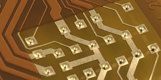
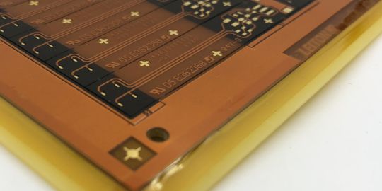
In contrast to rigid printed circuit boards (PCB), flexible printed circuits (FPC) usually do not use paint as a solderstop, but a yellow coverlay. The openings inside the coverlay for e.g. pads are cut out beforehand. This coverlay is then manually aligned and fixed over the copper image by hand. A yellow coverlay has the advantage that it is a bit more transparent, which simplifies manual alignment. Since this coverlay is then not cured by exposure to light, but is pressed on with heat, the advantages of green solder mask are irrelevant here.
Flexible printed circuits (FPC) are used to connect electronic components via copper tracks. At the same time, a flexible printed circuit can be a carrier of these components. Flexible printed circuit boards are bendable and can, in some circumstances, replace cables more efficiently. Due to very thin copper structures, they can be dynamically resilient, which, with a good design, enables many millions of bending cycles.
In contrast to rigid printed circuit boards (PCB), flexible circuit boards (FPC) are actually in the minority. A main function of any printed circuit boards, in addition to conducting electricity, is usually to “carry” electronic components. In principle, rigid circuit boards are more suitable for this because of their stability. Flexible printed circuit boards are used when a 3-dimensional connection of electronic assemblies is to be created, or when the electronics are to be "movable".
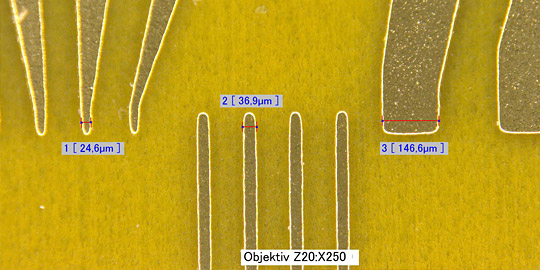
On the one hand, flexible printed circuit boards (FPC) differ in thickness. Very thin materials are only 13µm thick and therefore almost like wrinkled paper. Standard materials of flex PCBs are around 50 µm thick and offer a little more stability in processing and handling. Another difference is the material. Very cheap flex circuit boards are made of PET, but have technical limitations. Flex boards for industrial applications use polyimide (PI) as the base material, either with epoxy (adhesive-based) or without epoxy (adhesive-less/adhesive-free).
Flexible PCBs (FPC) are fully flexible/bendable and will only ever have any vias in these flexible areas (Note: the via areas are bendable but should not be bent as the vias may tear). With a flexible PCB, certain areas can be “stiffened” by gluing on thicker layers of polyimide (PI) or FR4 (this way, e.g. bending in these stiffened areas with vias can be partially prevented). In these stiffened areas, however, there are no vias through the entire board, but only through the flexible, thin part. A rigid-flex PCB (RFPCB), on the other hand, has rigid areas integrated in such a way that vias pass through the entire board, while the flexible parts are routed out of the rigid PCB.
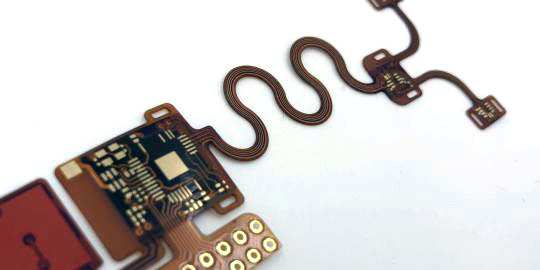
The advantages of flexible printed circuit boards (FPC) lie largely in the possibility of using them like a cable, but also being able to solder components directly onto them. Sometimes sensors that are needed in an area that is further away from the main electronics are soldered, possibly in a movable area. The flexible printed circuit board can then create the connection between the sensors and the electronics under dynamic stress. In other areas, flexible PCBs replace cables and are contacted with one another using suitable ZIF/LIF connectors.
The main component of industrial flexible circuit boards is polyimide (PI). Adhesive-free flex circuits (FPC) are made up of just the polyimide and the copper. More common are adhesive-based flex circuits, where the copper has been bonded to the polyimide using a layer of epoxy. These are called adhesive-based flex circuits. Another material is PET, which is usually only used for low-tech mass applications due to its low thermal stability and other disadvantages.
Flexible printed circuit boards are always manufactured individually according to the data supplied and go through many processes until completion. The costs at LeitOn for some prototypes start at around 200 EUR. However, if the flexible printed circuit boards are later mass-produced in larger quantities, they may cost less than 1 EUR or only a few cents. It is therefore difficult to make a general statement. If you are interested, simply send us your data or specifications and we will be happy to calculate the prices for you.
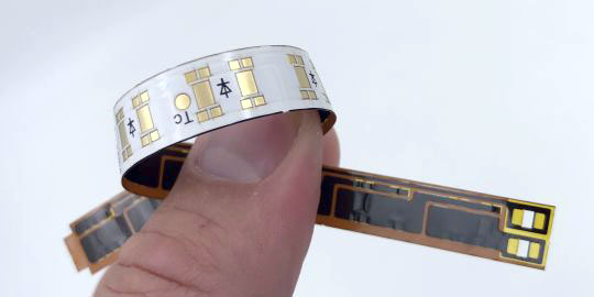
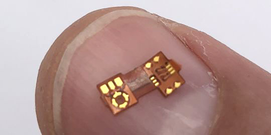
The most well-known application of flexible printed circuit boards (FPC), where everyone has probably held them in their hands, is on the printer cartridges of inkjet printers. Here you can see the flexible circuit board wrapped around one cartridge-corner in the typical brown-yellow color with some golden contacts. The flexible circuit board provides the electrical connection between the printer and the electronics (e.g. chip for identification) within the printer cartridge. In addition, flexible PCBs are used where electrical connections have to be made over flexible paths. Another classic example are today’s very popular LED strips, which are available in all kinds of colors, lengths and designs in every hardware store.

since 2021
- CO2 neutral through compensation
- Circuit boards – green on the outside, also on the inside

- Expertise through active exchange
- Expertise through training and further education
- ISO 9001:2015 Quality Management
- ISO 14001:2015 Environmental Management

- UL for rigid FR4 PCBs
- UL for flexible circuit boards
- UL for aluminum IMS boards


